3D Modeling Format Delivery
Custom 3D Modeling Format Delivery
Delivery Format Options
The data captured using either one or a combinations of the above technologies can be supplied in a variety of formats, such as generic STL, IGES, STEP, Parasolid or in native CAD format files such as SolidWorks, Inventor, CATIA or ProE, as a parametric feature based model.
Stereolithography (STL) Format
If you have the appropriate software then you can take the clean STL file from us and process it yourself. It is normally the case that the software must be point cloud specific. Some CAD system will import a STL file, but not perform any functions on the data other than viewing, and will either be very slow or crash as they will be overwhelmed with the quantity of data.
The STL format can also be fed directly into many CAM packages or to software to run a 3D printer. Although the raw STL data will not be perfect, for example planar areas will not be perfectly flat and there will not be any sharp corners generated in the STL unless the model has been significantly cleaned or a model created before saving the STL.
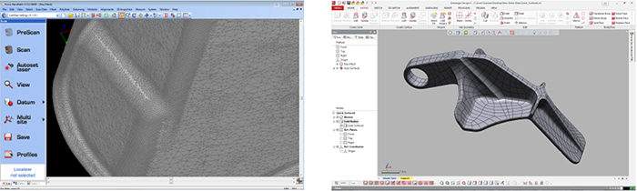
Quick Surfaced Model / NURBS patch layout
This is a method for getting a quick IGES/STEP/PARASOLID model that is tightly held to the STL file being used. So surface quality is dependent on STL quality.
The surface is created using a network of patches that are 'shrink-wrapped' to the data set. They are not modifiable in the CAD software, and would be used as a framework to create your own model.
Design Intent CAD Model
This will be a model that we create using the STL or probe data as a frame work, generating features such as planes, sections, extrudes, revolves, cuts and merges, to complete a solid body model.
Design intent will be applied to create a perfect model, with good planes, corners, fillets, and dimensions corrected in allowance for measurement inaccuracies.
Data can be delivered as IGES/STEP/Parasolid or converted in native CAD models for software such as Solid Works or Inventor, with feature tree as a parametric model.
Other Options
- The model supplied may be a standalone item or included in assembly structures with BOM.
- Sheet metal components/assemblies may be drawn as 'flat' pattern with assembly information including dimensions and weldment's and BOM.
- 3D acrobat PDF files can also be produced to allow users without CAD software to view the created datasets.
Please contact us by phone (817.416.8006) or email (sales@nvision3d.com) to discuss your 3D Scanning/Measurement needs.